Monday, October 28, 2013

To Build a Bridge Part VIII: Spanning Over it All

The main function of a bridge is to provide a navigable path over some dip in the terrain.  Be it canyons, water, traffic or anything else: the key component to the bridge is the "superstructure", the part that takes you over the open air.  As has been mentioned previously, there are many different systems that do this, but for this bridge, prestressed girders are used.

Prestressed girders stacked together.  At the ends are the prestressing strands.  Peeking out on top are "shear connectors", they help the beams integrate into the concrete deck that is poured on top of them.
These are concrete beams that have very high strength, steel strands running through them.  Reinforcing steel in concrete is normally "60ksi" steel.  That means it yields when 60,000 pounds ('k' represents "kips", which means 1,000 pounds) of force are applied to one square inch of it (yielding doesn't actually mean "failure", but we very rarely design above yield strength of rebar, and only for extreme events when we do).  The steel strands used in prestressed concrete have an ultimate strength of 270ksi.

A form is prepared for the correct shape and length of the beam.  Steel is put in: both the prestressing strands and standard reinforcing that will help with various forces and to make sure the beam doesn't crack or spall through temperature or chemical demands.  Then the strands are pulled on: adding tension to them.  Once the strands are at the correct stress concrete is poured into the forms around the steel.  Once the concrete has set, the strands are released and that tension transfers into the concrete, compressing it.

The forms surround the beams are strong, steel forms since they are compressed by the pretensioning of the steel strands.
Though prestressed girders can theoretically be of any shape and size, the designer is normally limited to just a few selections.  The DoT normally designs a few general shapes that they think are well suited to specific span lengths (the longer the span, the bigger the beam shape is).  The designer than chooses where or how much steel to put in that shape to make his or her bridge work.  By standardizing just a few shapes, local fabricators can build just a few forms of the appropriate shape, and then crank out beams quickly and cheaply.  For the Greenfield bridge, I choose "45W" girders.  This is WisDoT's specification for a girder that is 45 inches (just under four feet) tall and "wide flange".  These are pushing their limits at the ~107 foot span I had, but with enough steel they were up to the task.  The bigger the shape, the more expensive the girder.  More importantly, though, the bigger the shape the higher the road needs to be above a underlying highway, since the bigger shapes will impinge upon the clearance of the traffic below.  Thus, the smaller the girder you can reasonable use the better.

Prestressed girders have become the dominate bridge type.  Because of the ability of precasting plants to turn so many out so fast: they are very cheap.  By using fast-setting concrete, every form is expected to turn out one girder per day.  And do so for very little money once the initial investment in equipment has been made.  Almost every bridge from 40 or 50 feet to 150 feet is made out of prestressed concrete girders.  Bridges that aren't straight, or have some other, odd feature may still use another system.  But most bridges in that range (and most bridges are in that range) come from prestressed concrete.

Concrete is very good in compression, and very bad in tension.  That is the fundamental principle that underlies prestressed concrete.  It forces the concrete into compression before any load is applied, and allows for concrete to do what it does best.

Technically, prestressing doesn't actually make the beams any stronger than if you simply put all the steel in without prestessing it. The theoretical, final failure would occur at the same load.  However, by prestressing it you're making it so that the girders don't bend, deform and crack under normal loading. They are much stiffer, and much more resilient and elastic with prestressing.

So how much are the girders prestressed?  Well each bridge has to be designed, but for my very modest, Greenfield bridge, each girder had about 1.5 million pounds of force applied to it through prestressing.  That means the strands were pulled on with the weight/force of 750 tons, or over 400 cars.  As a point of reference, Greenfield had 16 girder lines and sports a surface area large enough to hold around 75 cars parked on top of it.

Tuesday, August 20, 2013

To Build a Bridge Part VII: Standing Tall

Any bridge with more than one span has a pier [Note: laymen will use the term 'span' to refer to an entire bridge.  Presumably because the term "Spans the entire width of the river" just means crosses the river.  But technically it means the place between supports.  So if there's a big pier in the middle of the river then there's actually two spans to get over the river].  Essentially just whatever is holding up the bridge between either end.  Some bridges have lots of piers, some have none, Greenfield has exactly one.  A pier can be many different things and built many different ways.  Unless it's an entirely timber structure, it's almost always made out of concrete (steel is inefficient for this application) but it can be shaped and formed and designed in all sorts of different ways.
The Lake Pontchartrain Causeways have a lot of spans and piers.
Typically the easiest and the cheapest pier for standard bridge uses a series of columns.  Taller bridges, ones crossing over multi-layered roadways or deep rivers and trenches, may use a single, very large column per pier.  Because Greenfield is wide and just crosses the one road: the multi-column approach was used (there are more approaches you can use, and a lot more subcategories, but this is good enough for a start).

Designing these piers requires looking at a large number of different loading patterns.  What if there's one truck pushed all the way over to the side of the road here, and no others?  What if there's one at the edge, but then one spaced 15' closer to center?  What about the wind loading?  What direction?  For Greenfield, I calculated (using some programming code I wrote, not by hand) around 50,000 different loading cases.  It doesn't scratch the surface of the number of possible combinations you could check under the code.  In fact, I calculated that if I checked every load placed to the nearest foot only, that it would be approximately 10^21 different combinations.
You can see the columns in various stages of completion.  The ones on the far end are poured and the forms stripped.  In the middle the rebar has been placed and forms placed around it that will give the column its shape.  On the close end only the rebar cage has been placed.
I'm actually responsible to make sure the bridge won't fail under any of those combinations, and there's nothing that says I only have to check to the nearest foot, if something spaced at 3 inches is more critical then that's my responsibility too!  This is where being an engineer actually means doing engineering rather than just calculating.  A sense of what controls, where, and what level of precision is required makes you a good engineer.  Being good at calculations just makes everything after the actual engineering easier.  In truth, 50,000 is way too many checks, but since it's the computer's time (and I ran my code in about 20 seconds) it wasn't worth taking hours of my time to pare down the possibilities to something more sensible.

The strength of the column is only counted for the section that is the same top to bottom.  In other words, that fancy looking, extra wide bit on top actually isn't designed to do anything.  When you see a column with a little cut running around the outside (if you look for them, you'll see these everywhere, from bridges to parking structures, to exposed building columns) know that this means that nowhere in the column is the outer bit considered for strength.  By cutting one inch out anywhere to make it look pretty, you're essentially wasting that concrete all the way up and down the column.
Of course if I'm wrong, and I excluded some critical case somewhere: that's on me.  Knowing that there are one hundred thousand quadrillion permutations isn't going to get me off the hook if something happens.  It's a sobering thought.

The columns are built to connect into the footings below (see To Build a Bridge Part IV: A Firm Foundation).  The rebar sticking out of the footing that now forms the column had to be placed before the footing was poured, so it's critical the shape and height are right, which can be hard to measure for thin pieces of steel sticking 20' in the air and moving around.
But here's the more interesting aspect of designing piers: the weight on the pier rarely controls the design.  For really tall piers that start to suffer from "slenderness effects" (the same thing that keep a sheet of paper from being able to hold much weight: it's plenty strong, but it deforms when load is placed on it) weight can control.  But for most pier columns, adding load to the column actually helps it stay up.

These are considered "slender columns", and for them, the total amount of vertical load will actually be critical.
Any one of the columns on the Greenfield bridge (there are seven in total) are rated to hold about six million pounds.  And that's what it's rated at, in truth it could support a lot more than that.  What controls the design of these columns are loads applied horizontally.  Temperature changes in the bridge superstructure that will push on the columns.  Vehicles braking on the bridge.  Believe it or not, wind controls the design more times than not.  Crash loads, where a truck simply breaks through the barriers around them and hits a column at full speed.  So if you want to see a bridge column break: don't keep loading up the bridge: just drive really fast on top of it and then hit the brakes.  Only we designed for that too so you're just out of luck.

Friday, August 9, 2013

To Build a Bridge Part VI: The Law of Bridges

You may or may not be familiar with building codes.  Across the world, just about every country has some kind of "code" that determines how and what you're allowed to build.  Want a shed in your backyard?  There will be laws about how high it can go, what it can be made out of, and how strong it has to be.  In the United States these codes are written on the state and local level (counties and cities get into the game too).  Well, building bridges has the same kind of rules and laws associated with it as building a shed in your backyard.  A little more complex but the idea is the same: the government has some minimum requirements for structures put up under its jurisdiction.  If you want to build your house out of straw you're probably going to get a visit from an unhappy inspector to inform you that it won't stand-up to the wind loads it's likely to see and maybe you should consider brick.

The Three Little Pigs is actually a story about the importance of government regulations and shoddy contractors
How do you determine what kind of traffic loading the bridge will see?  How do you decide what stresses your concrete or steel will experience?  How do you handle cracking in the concrete?  How do you know the section your designing is strong enough?  These may seem like questions that should be answered by just having an education in structural engineering, but they're actually variable depending on all sorts of assumptions.

You asked for concrete that can handle a compressive load of 4,000 pounds per square inch (that's called "4ksi concrete" and is pretty standard stuff, if a bit low-end) but what will actually show up?  You need to protect the reinforcing steel in the concrete from the elements so it doesn't corrode.  You decide to embed it far enough to be protected, but how far is that?  How long does it need to last and how fast do invasive chemicals penetrate the concrete?

When the concrete around the rebar falls off (typically this process is called "spalling") the rebar is exposed to the humidity and any other chemicals around, which for bridges, means the highly corrosive agents put down to prevent icing.  The rebar can deteriorate rapidly and loose the strength it needs to support the concrete.

That's what the code is for.  Every single state in the union has their own bridge design code because, apparently, physics changes depending on what state borders you're currently in.  It's really annoying.  But it's also not as bad as it sounds.  A group called AASHTO (The American Association of State Highway and Transportation Officials) has put together, and updates, a national code that determines all these things.  It is 1,600 pages long, and generally looks like this:

Knowing and following 1,600 pages of this is my job.  Now you know why engineering has such a high attrition rate.
This code is not the law, it's a document put out by an organization who has no legal authority.  At least not in that way.  But what most states do is adopt the AASHTO code as a body, and then have their own manual that goes on top of it to either clarify, add, remove, or otherwise change the provisions in AASHTO.  You can see Wisconsin's bridge manual here.  Once the state adopts any document as their code: it becomes law.  So most states say something like: "Except when our manual we've written differs from it, the AASHTO code is law". 

When we design a bridge, we have to "stamp the plans", which means literally stamping plan-sets and calculations with a "PE" stamp.  That's a professional engineering stamp that you get when you're licensed   Because each state has a different code, you have to be licensed in every state you want to work in separately   Most states, if you are licensed in another one, just require some paperwork.  Some states, in particular those with a lot of earthquakes (like California or Washington) will require a lot more than that.  By stamping the plans, you're taking personal responsibility for the design of that bridge.

Because the code is law: should something happen to the bridge, you don't necessarily have to prove that your design would work in the world, but rather that it conforms to the local code.  It's pretty rare that something designed to code falls down, but it happens.  In extreme events (mostly earthquakes)  and in some other, rare, instances like the Tacoma Narrows bridge.

The code is created after a lot of research and discussion.  A full discussion of code creation is a massive topic, which I will not be covering.  Instead I'll say that there are right ways and wrong ways to put together a code.  Bridge code isn't necessarily done the wrong way, but it's not the right way either.  Code for building design is, to me, a lot more elegant and efficient and produces a more consistent and usable code.  This of course changes from country to country: I'm only knowledgeable about US code.

There are various considerations when designing a code about how to lay it out, what to include, what to leave to the designer, etc...  One of the important descriptions of a building code is if it's "prescriptive" or "performance based".  A totally prescriptive code will tell you exactly what to do in all cases.  "For spans between 45 and 50 feet, use a prestressed, concrete girder of exactly these dimensions with exactly this reinforcing pattern and exactly this..."  A performance based code will tell you what is expected of the structure: "After a magnitude 7.5 earthquake, the girder can have cracks no larger than 1 inch".

The problem with prescriptive codes is that they can't actually cover everything, and so are both really expensive to build to (since they have to design for worst case uses which are probably rare) and leave little guidance or direction for uncovered cases.  Or just result in the under-design of situations the code-creators didn't consider.  Their advantages are that they're hard to screw-up a design with and are easy to use.  If boring.

If this bridge was designed to a rigid, prescriptive code, it likely would've fallen down.

The problem with performance based code is that it can be complicated to design with such little guidance, some aspects of design may not be considered when not spelled out by the code, and they open the designer up for more legal issues.  The advantages are they're much more flexible and allow for more accurate and efficient designs.  As well as giving a lot more guidance when working with unusual cases.  (When prescriptive code tells you that there must be rebar every foot of concrete no matter what that's what you put.  Performance based code would tell you that cracks can't develop that are larger than "x".  Thus, when looking at an odd scenario you have guidance from the performance based code about what you're trying to accomplish, and just a bar spacing from the prescriptive code which may or may not work).

No code is entirely one or the other once you get past assembling Lego models of Star Wars vehicles: they're all on a spectrum.  AASHTO is more prescriptive than some of the more sophisticated codes (I understand the Japanese have a very advanced, performance based code) but it has performance based elements as well.  And it's the law every bridge in the US is built to, or a modified version of it anyway.

Thursday, August 1, 2013

Building my Deck (Without Any Skills)

Despite my complete lack of experience and lack of handyman skills of any kind, I decided that I was going to build a deck for myself.  As a structural engineer I figured I could design a plenty sturdy deck, but how it actually turned out was... uncertain.  Judge for yourself!
A small selection of framing lumber I dragged home.
 I planned out a 20'x12' deck with a wrap around step.  My back door sits around 20" to 2' off the ground, and where the borders of the deck are: it would be closer to 14"-18".  That's enough that you need either a railing or a step and I had no desire to separate myself from my yard.  So a step all the way around would meet code and not make me take a circuitous route to get to my lawn.

Starting to dump the lumber where the deck would go
 There had been a deck there before.  A little smaller and it was structurally unsound when I bought the house so I had it torn out.  However, I didn't have to mess with the siding at all: which was nice.  I attached some 2x10s to the house with lag bolts and used that to support 2x10 stringers coming out from my house.  On the other end, I put down 4x4 posts into the ground and concreted them in for the foundation.  Then I laid a pair of 2x12s out on top of them as a kind of pseudo-ground beam.

The support at the house and the foundation at the end have been put in place and I'm beginning to run my stringers from one end to the other.

A side view of the ground beams and some stringers waiting to be attached.

A simple, shear connection at the house, these are 2x10s set every 16"

The stringers have all been laid.  They overrun the ground beam by about 2', this cantilever helps balance the forces between the house and the ground-beam and reduces the stress in the beam as compared with putting the foundation at the full 12' away.

The full frame (minus the steps on the end, you can see the ones at the side).  The board at the end of the stringers helps keep them from twisting under a load and locks the deck together.
For the steps I have no "in process" pictures of, but I created them by hanging 2x6s out from the edges.  Framing the steps took three times as long as framing the rest of the deck.  What a pain!  I used hurricane ties to attach them on the side where they'd hang from the exterior beam, and then rock upwards on the beam second from the end.  A couple of nails would keep it from wobbling, but there was no tension to worry about with that beam so no special connection was used.

On the end of the deck (opposite my house) I used three straps per beam.  Two on the outside to hold the beam up, and one on the back to keep it from moving (where again, it pressed into the beam, so no tension force to worry about).  The steps on the side I placed every 2' or so.  At the end of the deck, I simply attached one to each stringer.

Now it's time to screw in the deck boards.  Not much to it, but a lot of work.  It was about 1,300 screws in all.

Due to quantity and, most importantly, length, I  had this package delivered.  The deck boards are all composite which costs (three times) more, but there is no staining or upkeep and they essentially last forever.

Completed deck!  At the corners of the steps, I put solar lights in.

Seems like a decent amount of deck, right?

The composite board wasn't a bad match for the house.


Final costs are broken down here.  The deck screws I counted under "decking" but all other nails and screws went under "connections".  Masonry includes, in addition to the 400 pounds of concrete I poured, a bunch of bricks I was going to use but didn't.  Or haven't, I may put some down on the side of the steps.  Miscellaneous includes the lights, a little spray paint, some gutter stuff and the delivery cost for my deck boards.

Connections  $     257.60
Masonry  $        35.14
Lumber  $     487.90
Decking  $  1,894.80
Tools  $        89.50
Misc  $        87.40
Total  $  2,852.34

The deck was a 20'x12' deck with the steps for a total deck surface of just under 290 square feet.  So for a composite deck with me doing all the labor, the cost was almost exactly $10/square foot.

Tuesday, July 30, 2013

To Build a Bridge Part V: All Walled Up

A bridge, by its nature, is always going over something.  The vast majority of the time, this means that the height of the road approaching the bridge is artificially elevated.  That's true for water features or other natural crossing, but it is in particular, true for "grade separation" bridges.  Bridges where the point is to run one road over another.

Typically, the road surface beneath is lowered a bit by excavating out, while the above road surface is raised by adding "fill", which is just a slightly fancier word for soil (which itself is just another word for dirt, but as a geotechnical professor always told me: "Call it soil, no one is going to pay you to play with dirt").  However you do it, these kind of elevation separations require some kind of transition between the higher elevation of the soil above and the lower elevation of the road below.

This bridge (by Hoover Dam) has natural rock walls holding up the roadway leading onto the bridge.  Most situations require some kind of engineering to create a grade separation.

One solution is to just grade the soil down from high to low.  Which basically just means sloping the soil from high to low.  The old Greenfield bridge was this way, and some states, including Wisconsin, prefer this solution.  However, there are some draw backs to it.  Though it makes that transition cheap (essentially just the cost of some dirt) it takes up a lot of space and the bridge then has to span over all that extra distance.

Notice the span at the end.  Underneath that span, the "grade", meaning the surface of the earthwork there, slopes up from the road below to meet the road above.  In this case the slope is steep enough that concrete was placed on top to keep the soil from shifting.  The bridge needed to add an extra span just to go over this sloping soil.
The absolute steepest soil is typically allowed to slope upward is a 2:1 grade.  Meaning that for every two feet you move horizontally you can only go one foot up.  At this steep of a slope, you need to pour concrete on top of the slope to keep it from moving.  If it's just soil (no concrete or other binders) then 2.5:1 or 3:1 is where you need to be.  When you're in tight quarters, or just want to save costs on the bridge (by not making it span these extra distances) then you can save space by adding in a retaining wall.

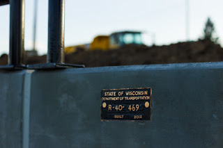
The name plate for the wall on the West side of the Greenfield bridge.  All states have some way of designating the structures they build.  Here the 'R' refers to "R"etaining wall, and the numbers indicate the region it's built in as well as a unique identifier that's assigned pseudo-randomly.
Retaining walls, meaning walls that keep, or retain, the earth from spilling over on top of whatever is beneath them, come in two, general varieties.   The first is a "cut" wall, this is when the earth is already as high as you want it to be, so you cut a wall into it and then remove the soil in front of the wall.  Greenfield has such a wall on its East side, though sadly I wasn't able to get any good pictures of it.
Building a cut wall, in this case a "soldier pile" wall.  When they've finished placing it, they'll excavate the soil in front of those steel piles: that's the"cut" portion of the wall.
At Greenfield, it was a "tangent pile wall".  This means drilling holes into the soil and filling those holes with concrete and rebar.  The holes are drilled tangentially to each other, i.e. touching each other, thus the name.  The bridge will sit directly on top of the concrete shafts, and so the wall is designed to resist both the force of the soil behind it and the force of the bridge on top.

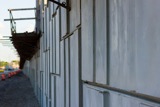
The West wall at Greenfield is a "fill" wall.  A fancy looking pattern is cast into the facing, but at it's structural simplest, this is just a collection of flat, precast, concrete panels all stacked up next to each other.
The second kind of wall is a "fill" wall.  Which is exactly what it sounds like: you put a wall where there isn't enough soil and fill it with soil.  Most such walls, at least here in the States (and my guess is this is true just about everywhere), are "MSE" walls.  With "MSE" standing for Mechanically Stabilized Earth.  The way it works is you take a panel (typically a 5'x10' or just 5'x5') that's around 5"-7" thick and attach straps to the back of it.  The straps can be just standard rebar, or the can be a specially designed plastic netting.  Their main purpose is to engage the soil that's going to go behind the wall.  Or in other words make it so that when the panel gets pushed out by the weight of the soil behind it, it pulls on the soil, whose weight stops it from actually going forward.  In other words: the soil anchors itself.

A panel with straps is placed with no soil behind it.  Then a "lift" (or layer) of soil is placed on top of the straps and compacted.  It needs to be compacted because it will settle eventually and you want to make sure there are no gaps, no strange settlements, and that the final surface of the soil doesn't change elevation.  Then, when that panel has been filled up, you place another panel on top of it and put down some more lifts.

Because space is at a premium both from an availability and cost perspective, transportation-related walls tend to be straight.  But nothing says you can't slope them.

Like the bridge, the soil you want around the wall itself is sand to ensure drainage (an actual drain is placed along the back of all these walls, leading to an inlet somewhere that connects into the storm drains).  But the wall has additional excavation behind the actual, stabilized part, and that can be just about any kind of soil.

Many situations, if not most, aren't clearly in a "cut" or "fill" category.  Maybe there's a soil layer that goes up 8' but you need 20'.  In those cases, and in fact in every case, it is function followed by cost that determines what kind of wall you use.  The actual function may just be to hold up soil, but it could be it also has to allow utilities to travel behind it or bear the weight of a structure.  If that's the case, sometimes more expensive walls are used because the cheaper versions aren't as functionally flexible.  For a fill wall, there has to be a lot of excavation behind the wall itself (remember the 2:1 thing?  That holds true for temporary, construction situations as well, though contractors will try to get away with 1.5:1 or sometimes even 1:1 slopes).  There's not always room to do that, especially for very tall walls.

After function is determined and met, cost drives wall selection.  There are many situations where the wall is in an entirely cut condition, meaning the existing soil level is already at or above what will be needed in the final condition, but a MSE (fill) wall is used.  MSE walls are really cheap, and so any chance to use them is jumped at.  It seems a bit silly to excavate all this soil to build it and then fill it back up,but that is often cheaper than building a cut wall.  So Greenfield had one cheap wall (MSE) and it also had the most expensive wall type we use: the tangent wall.  A nice mix.

Sunday, July 21, 2013

To Build a Bridge Part IV: A Firm Foundation

As I mentioned before, the bridge is (in a very general sense: you skip around a lot) designed from the top down.  But it's built from the bottom up, and while the bridge-using public doesn't see it the foundation takes a fair bit of design.  This is where geotechnical engineers get into the game: they're the ones that calculate the strength of the soil and rock in the area.

Any project, once it's decided about where the bridge/wall is going to be, starts with some soil borings.  This essentially means take a drill rig and drilling into the earth some specified distance.  Every so often (1.5-5 feet it typical, depending on whose ordering it and how deep you are) a soil sample is taken and analyzed.  The main property being tested is the strength, which is inferred from multiple different measurements.

For a wall, a 30' (for those not "in the know", an apostrophe represents feet and a quotation is inches, so 30'-6" is 30 feet and 6 inches) boring is typical.  For a bridge, 100' is not uncommon.  Some footing types even require deeper borings, but that can get expensive quickly as equipment that goes that deep isn't cheap.

Piles sticking out of the ground for the West abutment foundation.  The piles have an estimated length they're supposed to be driven, but you don't stop until you hit a certain level of resistance.  Thus, most piles end up with a lot of extra length on them (you can see where the top of wall ends, the piles are supposed to be at about that elevation) and are cut off when it comes time to build the foundation around them.
 A "footing" is the part of the bridge that transfers the force from the structure to the soil.  A pile is a structural element that goes deep into the ground.  Above you can see steel, tube piles sticking out of the ground where the West abutment will go.  They terminate somewhere well beneath the surface.  The estimated lengths to "drive to capacity" are around 70' here.

Pile driving is exactly what it sounds like.  You take some amount of pile, stick it into the ground, and then continue to pound on it until it drives in deep enough to take the load.  Essentially you just put a pneumatic hammer on top of it and turn it on.  The hammer measures the resistance, and when you get enough you turn it off and start on the next pile.  They don't start with 70'+ long piles, they're much shorter.  As the pile starts to get close to running out of length, they pause the process and weld another length of pile onto the current one.

Drilling a concrete shaft for the pier footing
 But piles aren't the only way to support a structure.  This bridge actually started off with a "shallow foundation".  That essentially means something where you aren't drilling or driving, or doing more than excavating 5-10' down into the ground.  The original design called for a mat footing underneath all those columns that are going to be at the pier.  This essentially means digging out a place to put a 4'-5' deep concrete pad (as I recall, it was about 12' wide and spanned the whole, 136' of the bridge width from side to side).  That way, the weight from the bridge is supported entirely by pressure from the soil right there.

But we had to make a last minute change.  There's a 60" sewer pipe directly beneath the pier foundation.  Originally that was going to be grouted up (filled with a cementitious material: essentially turning it into a long, cylindrical rock) as it's old and a new one is coming to replace it.  But just before the project was bid, some guys in the utilities world decided they wanted to keep the pipe in use for another couple of years before closing it off.  We weren't sure the pipe could take the extra stress that would come from loading the soil on top of it (our shallow foundation) so we switched foundation types.

The edge of the wall can be seen in the foreground.  Most walls do not directly support the bridge, instead the force is transferred down behind the wall to the soils deep beneath it.
 To ensure accurate placement and sufficient strength, we went to drilled shafts.  These are shafts (here they're around 3.5'-4' in diameter) that are drilled into the ground to a specified depth (around 60-70').  Because nothing is being driven, you can't cut out early if you achieve capacity at a shallower depth than what's estimated.  Once the shaft is drilled it's filled with rebar and concrete, and you build the footing on top of it.
This specialized equipment was driven out from the Rockies, once the driller has done it's work, a rebar "cage", pre assembled steel bars, will be lowered into the hole and concrete poured in to fill it up.
If you can place your structure directly on bedrock you'd love to do so.  But in Southeast Wisconsin that's just not feasible (it's way too deep to reach) so the geotechnical engineers will give you a graph that tells you expected levels of support for a given pile type and size versus the depth you take it to.  It's then up to the structural engineer to pick the foundation type and design the pile if necessary (steel piles aren't designed: just counted, but the reinforcing in the drilled shafts have to be designed).

When you've built your foundation, you fill up all the excess area with sand and get started on the rest of the substructure.  The sand has all sorts of fancy names and criteria but it's essentially just sand.  Despite the parable, sand is actually a pretty good material to build on, but more importantly: it drains water.  You take a lot of precautions to avoid having water just sit right next to your concrete footing.  The concrete doesn't mind (as long as it doesn't freeze and thaw too much) but eventually the water penetrates and hits the rebar.  This is bad.  So you put quick-draining materials everywhere and then make sure there's a piece of perforated drain pipe somewhere nearby to take all that water away from your structure and get it out of there.


Sunday, July 14, 2013

To Build a Bridge Part III - Coming Down and Going Up


Jackhammers demolishing the deck of the old, Greenfield bridge
The first step to building the new Greenfield bridge is getting rid of the old one.  The new bridge is going to be bigger, and built to an updated code, but there was already a bridge there.  It will be down for about 6 months while the new one is put up.  This is fast, but does not really fall into the realm of "accelerated bridge construction" (ABC).  I just means the crews will be working a little harder, or with a few more people on staff to get it done.


A look at the equipment and the bare girders behind it with the deck stripped off.
Because the bridge crosses an interstate, they have to work fast.  Demolition can only happen with traffic beneath shut-down.  So the state gave the contractor two night closures in which they had to demolish the entire bridge.  They can clear up the rubble and cart off the old material after it's down, but following two nights of work: there should be nothing standing over the interstate.


After night one: the girders over the interstate remain as well as the piers.  The old deck with its rebar is sitting in the foreground waiting to get carted off.
But with it down, the question at hand is: what will replace it?  Bridges can be all sorts of different lengths, heights and widths.  As discussed before this kind of geometry is set by roadway engineers who try to fit the bridge into the minimum necessary space.

Most bridges people know, or think about when asked are long, impressive looking ones.  These are often referred to as "signature" bridges.  A signature bridge is one in which a lot of extra money is put in to make something unique and beautiful.  They can be shorter if they're in a prominent location and the powers that be want a specialized look (an example from my neck of the woods is the Milwaukee art museum bridge).  Some bridges can't help but be signature-style bridges due to their immense length.

Most bridges, however, are not signature bridges.  They are designed to be as cheap as possible, with maybe 1% of cost added to make them look vaguely appealing to the public.  That aesthetic improvement typically coming by adding relief patterns to the columns and staining the whole thing what are deemed to be pleasing colors.  Thought is given by the designer to how things will look, but that isn't likely to be a controlling factor unless the cost and construction considerations of the choice are essentially zero.  And that tends to only be true for details that the public is unlikely to notice.

The old, steel girders with shear studs that used to connect them to the deck.
When the bridge type is chosen for a new bridge there are various different factors.  There's the overall length of the bridge (from abutment to abutment: essentially the distance you're not on ground) but the more important value is span length.  The distance between substructure units.  Designing a bridge that is is a mile long is easy if there are no spans longer than, say, 100 feet (from a structural perspective, it's still a pain to produce plans for all that bridge).  A mile long span is essentially a signature span by definition.  There are, in fact, only three bridges in the world with spans of a mile or more: it's expensive and complicated.

The shear studs are designed so that when the girders bend, the concrete above would bend with it, thus you can take advantage of the added strength of the deck when designing the girders and save money on steel.
The geometry of the bridge is also important.  "Skew angle", meaning the angle between the direction of the bridge and the angle of the substructure units can be important if it's very large.  Here's an example of a highly skewed bridge; notice the non-perpendicular angle between the girders running across the river and the abutments supporting them on either side.  The farther off of 90 degrees it is, the bigger the skew.  Geometry would also refer to the bridge curving horizontally over its length.

The metal beams in between the girder (the smaller steel connectors that connect the bigger ones) are there for construction only.  They keep the girders from tipping over before the deck is placed.  Once the deck is there they serve no purpose, and can actually have negative consequences due to various fatigue considerations.  But pulling them out is hard and expensive so normally they're left in for the life of the bridge.
When spans are greater than 30 to 50 feet, and less than about 120 feet, every state will have a preferred bridge type.  In fact, up to around 250 feet most states are likely to have prefered types that change with the span length.  But the sweet spot is 50-120 feet, because that's the range that most highway bridges fall in so there are a lot of them.  And making them all (or as many as possible) the same type can save a lot of money.  Bridge selection (what kind of bridge to use) is almost always driven by cost.

Most states use prestressed, concrete girder bridges in this range.  A few with big steel industry in their state will use steel girders.  Wisconsin does not have a big steel industry so concrete girders are used in this range.  All bridges are made out of steel and concrete.  There are a lot of fancy materials out there, but nothing can compare to steel or concrete for their strength-to-price ratio.  Other materials are used in small capacities (like using rubber to seal joints to keep water out) but structurally it's always concrete and steel.

The steel is cut using a flame-cutter.  This is essentially an acetylene torch that you can blow compressed air through.  You heat the metal, and when it turns liquid, blow it away: cutting through whatever piece you're working on.  The flame-cut ends are visible here.
When someone says a bridge is "steel" or "concrete" they're referring to the superstructure.  The part of the bridge that actually does the work of carrying the massive load across the span.  The old Greenfield bridge that is shown here being demolish is steel, the new one will be concrete.  No bridge is actually all concrete or all steel.  If it's concrete it needs steel reinforcing bars (rebar) or it can't take the load.  If it's steel, it will still have a concrete deck and substructure.

Each material has different ways it can be used.  Very short bridges are normally "slab" bridges.  Essentially the deck is made strong enough to carry the whole load without any girders beneath.  Then you get to traditional girder bridges like both the old and new Greenfield bridge which have these girders running the length and supporting the deck above.

As the spans get longer, the girder shapes change.  A typical girder is shaped like an 'I' (see the above pictures), a thin 'I' if it's steel, and big, overweight 'I' if it's concrete.  Longer spans, or ones with horizontal curves (and some very highly skewed bridges) will switch to "box" or "tub" girders.  When you start to get above 250 feet you start to get into fancier and fancier systems, moving away from girders entirely.

But Greenfield isn't fancy.  It will be wide, but it's a work-a-day bridge and so it will use, as much as possible, all the standard, WisDoT features of a normal length bridge.

Tuesday, July 2, 2013

To Build a Bridge Part II - Where's it going to go?

The Greenfield bridge is part of a massive rebuild of the "Zoo Interchange" located at the Northwest corner of Milwaukee.  This, the Greenfield bridge, is one of the first projects out the door for the interchange and part of the reason is that it's greatly increased capacity will help mitigate traffic problems when the Zoo interchange itself shuts down for reconstruction.

The process that decides this involves a lot of people.  And some of it is politics which is not my forte, but most of it is engineering, and that is.  The road layout, the position of sidewalks, the width of the traffic lanes all factor into positioning the bridge.  Some people seem to think that we basically show-up, see a space, and throw a bridge in there.

This is not the case: the roadway is planned out with several considerations.  First, of course, is the size of the road.  Traffic patterns are predicted about 25 years in advance and total lanes needed to accommodate that traffic are estimated and (if in budget) provided.  Sight lines horizontally and vertically are checked to ensure that national codes are met.  These relate to the amount of time a driver needs to see an object of a given size and stop (or otherwise avoid it).  Time to merge or turn is calculated based on road design speed (which is different from the posted speed limit) and things like crash protection and shoulder size is determined based on estimated traffic speeds.

Every aspect of the bridge is laid out to the nearest 1/8th of an inch.  It's a bit of a surreal feeling to be sitting in a building, miles away, specifying where the edge of a concrete barrier will be to the nearest eighth of an inch.

Every bridge has pages of plans drawn up specifying every bit of concrete, every single piece of rebar, every bolt and patch of rubber.  Those plans are public record, but they aren't posted yet.  I do have a copy, but I'm not sure of what my legal right is to share them, so ... I'll show one page here.  From an old set.

One of what ended up being about 40 pages of the plan set

From the roadway engineering perspective, it's essentially a question of fit.  They want to accomodate 'x' number of lanes going in 'y' direction, passing over/under 'z' road.  The department of transportation for Wisconsin (WisDoT) already owns some amount of land, and while it's expensive, they can use eminent domain to buy more.  But the goal is to help out the area, not destroy homes or business, so an attempt is made to buy and clear as little land as possible.

The roadway engineer (which I'm not) will work with the structural engineer (which I am) to make sure that a bridge will fit in that area, and have enough space to support it's weight.  Position of columns, decks and girders are taken into account and a horizontal and vertical profile is created that is supposed describe all the driving surfaces in all three dimensions.

Once the geometry of the bridge is determined (and this is actually an evolving process, that goes back and forth over the course of the design, but in theory it's linear) the structural design starts.  In construction the bridge is of course built from the ground up.  But it's designed from the top down.  Meaning the function is considered first (function being the driving surface) and then what's needed to make that function is designed.

Once again the process is iterative, as the design of the substructure (the piers/columns supporting the bridge, abutments or supports at either end, and anything in the ground) may influence what has to be done on the superstructure (anything above the substructure).  Part of being a good engineer means being able to make good estimates for things you haven't designed.  For example, if I was told that the desire was to span about 100 feet, I'd guess that we'd need a superstructure that was 5 feet deep to do so.  A roadway engineer could then design her vertical profiles to ensure that there was enough clearance between the bridge and the road beneath it.  As I refine my design, I may discover that I only need 4 feet and 9 inches.  The choice can then be made to lower the bridge, or to leave the excess clearance in.

Some bridge terminology

But I'm getting ahead of myself.  While the design came before anything was done in the field, the field had to start off by clearing the old one.  The road was going to be widened but not re-routed, so the destruction of the old bridge needed to be done before a new bridge could be built.

Sunday, June 16, 2013

To Build a Bridge Part I - Intro

Whose bridge is it?

The bridge carrying Greenfield Avenue over USH 45 in Milwaukee County, Wisconsin
The above is the bridge to be replaced in this little series.  It is aging and showing it.  Right now it is structurally just fine (even if parts of it don't really look like they are) but it's old and will soon be far too small.  So it will be be taken down and replaced with a new, better, bigger bridge.

But whose bridge is it?  The taxpayers (largely through the gas tax, but also with state and federal money) will be paying for it, the state department of transportation (WisDoT: Wisconsin Department of Transportation) owns it.  Which is another way of saying the people own it.  The state legislature passed the bill that payed for it and it was the Governor that pushed it through and signed it.  A construction company got the contract and will actually build it; them and their subcontractors.

Anyone on that list can call it their bridge and be right.  But I'm the designer: I ran the calculations and assembled the plans and laid the whole thing out so it's my bridge.  Not mine alone, but it's certainly mine.  And what I'll try to do here is explain some basic things about bridges using this one as an example.

If anyone has questions about what I say, wants a clarification, or wants to suggest another subject they'd like to know more about, feel free to leave a comment.

Saturday, May 4, 2013

Draining the Sump

When I had my home inspected (prior to purchase) the inspector found that the previous occupants had disconnected the sump pump from the drain and now had it empty into the floor drain.  A rather curious choice since the floor drain basically drains back into the sump.  Presumably the original drain had gotten clogged and either instead of fixing it, or just as a temporary fix until they actually fixed it (and then they died before they got around to it) they decided on this solution.

Part of the contract for the sale was that they take care of this problem prior to me moving in.  I assumed they would clear the old drain and re-hook the sump pump to that.  Instead, they ran PVC pipe around the inside of the basement, cut a hole in the side of the house and had it dump the water out there.  It wasn't a very pretty solution but it's an unfinished basement so I shrugged and forgot about it.

A few times this winter the basement got pretty wet.  There was never standing water, but anything absorbent on the basement floor would be completely saturated.  I meant to figure out what it was, but it would go away and I would forget.  Finally, a few weeks ago, we got a week plus of continuous rain.  I was lucky again in that there was no standing water, but I saw little streams making their way across the basement and I realized I was getting pretty close to a pretty serious problem.  Besides the mold threat.

So a little thought and I realized that the new sump drain was dumping the water about five feet away from my house into the stone surrounding it.  This was a little better than just pumping it into the floor drain but the problem was essentially the same.  It might take a little longer, but the sump was basically getting drained into itself.

I took 25' of gutter extender I had leftover from when I was insulating my house and stuck it on the end of the sump drain. It gave me another 20' or so the water was being pumped away from the house.  The next week we had another multi-day downpour and the basement stayed dry.  So I had found my solution, I just needed something a little better than some gutter extender sitting on top of my lawn.

This Saturday I had the time and the weather and I'd run out of excuses, so I got at it.  The good solution was to attach more PVC pipe and run the line down the drainage ditch at the front of my yard.  I picked the slightly easier and cheaper solution of running 4" black drain pipe down to the ditch.  I still needed to bury it though, and that was going to be the problem.

The first two thirds of sod are removed.  You can see the gutter extender draining onto my driveway in the background.

I started by digging the trench from where the pipe exits my house to the slope at the edge of the ditch.  Digging an 8" ditch was depressingly time consuming.

What pretty pieces of sod.  I'm sure they'll go back just as well as they came out.

I tried to cut out the grass in nice, rectangular pieces.  I was going to have put these back once I buried the pipe so I couldn't just tear them out.  I'm not sure how successful I was, but I created a lot nicer looking pieces of sod at the end than the beginning.   

A line of sod, a line of dirt.  I'm sure this is symbolic of something.

After I'd converted a line of grass into pieces of sod, I went back and dug the trench deeper to allow for the pipe to go  under the sod once it was replaced.

Can you even see where the trench is?  Honestly?  OK, what about if you lie?

I failed to take a picture of the newly-laid pipe itself, but here it is with the sod put back on top.  I don't know how well it will work out.  Worst case scenario I'll have to re-seed that line in the grass once the soil settles.  The line drains to a few feet below the top of the ditch and seems to be working fine.  So hopefully wet-basement problems are a thing of the past for me.

Sunday, April 28, 2013

Building a Fire Pit

I've had it in my mind to make myself a little fire pit for a while now.  Not a large project, but still it took months before I actually got around to doing it.  In the end, I did it all in about three hours counting the time it took to drive to Home Depot, buy the stuff, place it and clean-up.  A small project, but a rewarding one.
So far as it appears, I can't tell the difference between a construction project and a hole in the ground

I dug a pit in my backyard, maybe 8" deep.  I tried to keep the bottom level, but since the ground slopes slightly I imagine the result was less than perfect.  Still it was close enough, and after about 15 to 20 minutes I had a roundish, 3.5 foot diameter hole.

Fire pit parts: some assembly required

I went to Home Depot to acquire supplies.  I actually had to buy a wheelbarrow as I had not gotten one previously.  Which meant attaching my trailer to my car and getting my usual angst as I drive around the very bumpy local roads.  But I got the trailer to the store and ended up with 64 bricks, a pitch fork, some "leveling sand", a 5-gallon bucket and some mortar with a bin to mix it in and the trowel to place it.


A wonderful day to do the work

I placed the leveling sand around the edge of the pit as well as in the pit.  Then it was time to really get going.  I had bought two, 60 lbs bags of mortar, but I only needed one.  I mixed in one batch and started applying it.  It was obvious I wasn't much of a mason, but this didn't exactly need to withstand armageddon  so within the hour all the bricks had gone up and all the mortar had been slathered around between them.  I had guessed on the number of bricks and by sheer luck: gotten it exactly right.  I used every one of them, and they were placed perfectly to allow for three courses with a small opening in each one to let some air move through.

The mortar is applied and is beginning to set

I cleaned up as best I could: removing excess mortar and ensuring the bricks were placed where I wanted.  Then nothing to do but clean-up and wait for the right time to put my creation to use.

I invented fire!
 When night came, I started a fire up and made smores.  Yum!  Day well spent.